| |
excessive wear at this time. If necessary, they are scaled
and cleaned of rust and other foreign matters, checked
for excessive wear or corrosion and, where conditions
warrant, replaced with new ones.
Disassembly of detachable links in the outboard
swivel shot with hairpins requires removal, and
probable destruction, of the lockwire. The availability
of replacement wire of the same type should be
established before removal for inspection of the
detachable link. Replacement hairpins can be fabricated
on board ship from corrosion-resistant steel.
Anchor chain and appendages are carefully
examined for cracks, excessive wear, distortion, or
other defects. Parts that require coating are painted with
anchor chain gloss black paint. Shackles, bolts, locking
pins, and swivels are examined carefully and put in
order. The turnbuckles in chain stoppers require
frequent attention to keep them clean, free from rust,
and well lubricated with a graphite grease.
Chain of sizes by more than 1 1/2-inch wire
diameter is overhauled, wire brushed, and placed in a
good state of preservation as often as required. At least
once every 18 months all anchor chain, regardless of
size, (including all fittings) is examined, overhauled,
and placed in a good state of preservation (5 years for
carriers). To distribute the wear uniformly throughout
the length of the chain, the shots are shifted to a new
position as necessary during this inspection. If, during
overhaul of the chain, significant defects are
discovered, they are brought to the attention of the
Naval Sea Systems Command. If it is not practical to
make immediate replacement, the defective shots are
shifted to the bitter end of the chain. Chapter C6,
Volume 2 of OPNAVINST 5100.19 (series) (NAVOSH
Program Manual for Forces Afloat) contains safety
precautions on ground tackle.
ANCHOR WINDLASS
Windlasses are installed on board ships primarily
for handling and securing the anchor and chain used for
anchoring the ship and for handling anchor chain used
for towing the ship. Most windlasses have capstans or
gypsy heads for handling line in mooring and warping
operations.
Windlasses can be located on the stern of the ship
for stern anchoring, but are usually located in the bow
of the ship for handling bower anchors. Windlasses also
handle bottom-mounted braided fluke anchors (keel
anchors) used on submarines (stern) and some surface
ships (bow).
Landing ships capable of beaching have a separate
anchor winch to handle the stern anchor used for
retracting from the beach.
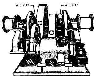
Two general types of windlasses are installed on
naval ships. They are the vertical shaft and the
horizontal shaft types. See figures 4-10 and 4-11. These
two types are subdivided into classes, depending on the
power source. These classes are electrohydraulic drive
and electric drive. The essential parts of a typical
windlass, regardless of its type and class, are the drive
motor, wildcat, locking head, hand brake, capstan or
gypsy head, and control.
Horizontal shaft windlasses are usually made as a
self-contained unit with the windlass and drive motor
mounted on the same bedplate. Vertical shaft
windlasses have their power source located below deck
with only the wildcats and capstans mounted above
deck.
The windlass wildcat is a special type of drum or
sprocket constructed to handle the anchor chain links.
The outer surface has flats (or pockets) which engage
chain links. At each end of the pockets, lugs (known as
whelps) are provided, which contact the end of the flat
link. A central groove in the outer surface
accommodates the vertical links which are not in
contact with the wildcat at any point.
Windlass wildcats have a locking head for
disengaging the wildcat from its power source. The
locking head permits free rotation of the wildcat when
you are “paying out” the chain. Locking heads usually
consist of two sliding block keys that may be shifted to
key together a drive spider and the wildcat. The drive
spider is keyed to the windlass's shaft, while the wildcat
Figure 4-11.–Horizontal shaft anchor windlass.
4-9
|