| |
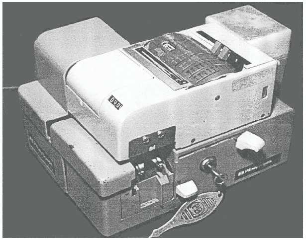
Part 8: COUNTER WINDOW. This counter advances
once each time you produce a meter tape. This counter
cannot be reset manually.
Part 9:
METER MANUFACTURER.
The
manufacturer’s logo and name are engraved on the
meter.
Part 10: SERIAL NUMBER. The meter head serial
number is also engraved on the meter and is usually
located above the high denomination button.
Each
meter head has its own unique number. Each time a
meter tape is produced, this serial number is printed on
the tape indicating which meter produced it.
The following are parts of the meter base:
Part 1:
TAPE AND INKER COMPARTMENT
COVER. This cover protects the ink rollers and meter
tape from being damaged. By grasping the upper-left
portion of the machine and pulling it out and to the left,
both the tape and inker compartments are exposed.
Part 2: INKER. The inker assembly consists of two
absorbent rollers that are mounted on a metal bracket.
The larger of these rollers is saturated when new, with
enough ink to produce approximately 15,000 tape
stamps.
Part 3: WATER CONTAINER. This container is used
to moisten tapes when the deflector switch is in the
“WET” position.
Part 4: CUSTOMER’S LOCK. This is a cylinder lock
used for locking the meter on the machine and to lock
the machine against operation. To place the machine on
the “lock” position, shift the operating lever (Part 5) to
the center position between OPERATE and REMOVE,
then turn the key clockwise one-half turn and remove
the key.
Part 5: OPERATING LEVER. This lever can be set at
one of three positions, REMOVE (forward position),
LOCK (center position) or OPERATE (rear position).
The operating lever engages the meter to the machine
when it is moved to the extreme rear position. This lever
must be moved fully forward when you wish to install or
remove the meter or when you wish to engage the meter
when it has been secured.
8-17
PCf0808
Figure 8-8. An example of a meter head engaged to the meter base.
|