| |
to understand. The programmer controls and
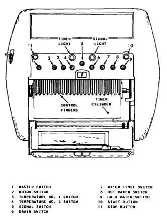
indicators are shown in figure 5-21. The door to
the programmer is open so you can see the
controls on the inside. Machine controls are
located near the supply injector; as we discuss the
controls, follow along on the illustration.
1. Master switch—This switch (No. 1) con-
trols power to the machine and has three
positions:
MANUAL—machine functions controlled
by switch settings
OFF—power off
FORMULA—machine operations con-
trolled by timer and precut program chart
2. Motor switch—The motor switch (No. 2)
controls power to wash, drain, and extract
motors. It also has three settings:
WASH formula-washer operates in either
auto or manual mode
EXTRACT—this powers extract motor in
manual mode
OFF—power to wash, drain, and extract
motors de-energized
3. Temperature control switches (Nos. 3 and
4)—These switches control water temperature.
They
4.
have three settings for each switch:
ON—used during manual mode to control
preset temperature
OFF—no temperature control
FORMULA—temperature automatically
maintained according to the program chart
Signal switch (No. 5)—This switch is used
to cancel and signal what has been called for on
the program chart and allow the Milnor motor
to resume operation.
5. Drain (No. 6)—The drain has three
positions: OPEN, SHUT, or FORMULA. In the
FORMULA position the drain opens or closes
according to the formula.
6. Water level switch (No. 7)—This switch has
three positions: HIGH, LOW, or AUTO. The
Figure 5-21.—Milnor controls and indicators.
HIGH and LOW positions are used in manual
mode while the AUTO position admits water
according to the program chart.
7. Hot and cold water switches (Nos. 8 and
9)—These switches control opening and closing
of hot and cold water. Both switches have three
positions:
8.
when
timer
9.
IN—opens hot or cold in manual mode
OFF—closes hot or cold in manual mode
AUTO—opens and closes either valve
according to the program chart.
Signal and timer lights—Signal light is lit
machine requires operator attention. The
light is lit when the timer is in operation.
Thermometer—The thermometer auto-
matically controls preset water temperatures
5-28
|